
Destination
This is the technical support page for the Microwave Generator device. The generator is low cost microwave signal source for use in physical experiments iside racks of equipping. It is built on the based YIG oscillators of companys: "Stellex", "Giga-tronics", "Micro Lambda wireless" with maintenance of frequency PLL synthesizer. Possible use frequency range in interval from 6GHz to 12GHz, by connect required YIG oscillator. Device includes onboard TCVCXO (temperature-compensated voltage-controlled crystal oscillator) with +/- 100 ppm tuning range.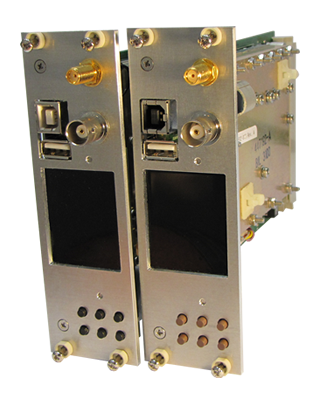
Parameters
| Parameter | Value |
|---|---|
| Frequency range | 2.. 12Ghz |
| RF output level | +8.. +14dBm |
| Phase Noise @10K | –92 dBc/Hz |
| Phase Noise @100K | –114 dBc/Hz |
| Frequency step range | 200kHz.. 4MHz |
| Reference clock | 10 MHz, +/-25ppm |
| Modulation | DSP DAC, up to 25mHz |
| Microwave oscillator | MiniYIG type |
| Control interfaces | Buttons, Network Socet |
| Operation system | Embedded uClinux |
| Operational voltage | 15V & 5 Volt |
| Dimensions | 137mm x 54mm x 40mm |
| System connection | Ethernet cable |
| Software | Linux, Windows |
| Graphics Display | 24-bit RGB, 128x160 |
Phase noise distribution
Below are graphs of oscillator noise measurements at different distortions for several comparison frequencies.
The PLL phase noise diagram
Usage
Insert the device to equipment rack, enable power and little wait, while internal OS loading.When graphic interface started, push any button for call control menu.
1. Use button: < / > for select frequence digit to modification.
2. Use button: + / - for change value. Setup have remember and auto save.
3. Use button: OFF/ON for YIG generator power shutdown.
Software automaticaly change output frequency depending on current REF-frequency value. If reference frequency equal 1MHz, accordingly +/- 1 step equal 1MHz. REF-frequency also possible change and get fractional frequency output.
Modulator usage
It is impossible to guess in advance what kind of signal may be required for modulation. Use the built-in DAC to modulate the microwave signal. To be able to create fast signals, the device is built on the BlackFin DSP processor. Add an application to create your modulating signal and using the built-in DAC driver run the file for execution.Remote Control From PC
1. Connect to rack backplane ethernet cable accordingly doc: "Cable connection sch".For fast launch use LAN Backplane cable extender, this board available in electronics support office.
2. Only one the RF-generator device can be used with one ethernet cable line.
3. If ethernet cable soldering properly, you can see device IP address on display.
4. Use IP for connect to device by
 PuTTY or any similar software.
(SSH, port 22, root psw:1) or (FTP, port 21, root psw:1)
PuTTY or any similar software.
(SSH, port 22, root psw:1) or (FTP, port 21, root psw:1)5. Use utility "rfcontrol.exe" for direct device control from your application.
Launch this utility with -h option for viewing help. Project source code also contain how-to example.
Tuning and Configuration
The generator runs on Linux operation system and can be servicing like ordinary computer. RF PLL controlled by application with name "pllcom" and read settings from configuration file: /etc/pllcom.conf. Change this file for yours case. You can connect an external stable Reference Oscillator, then your microwave frequency will be very accurate.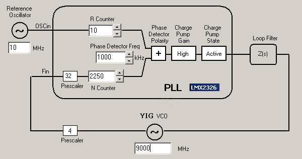
The PLL structure diagram
Use an auxiliary utility to verify the feasibility of setting the required frequency. By adjusting coefficients R and N, aim for the maximum alignment with your desired value. Fine-tuning of the frequency can be achieved by modifying the TCVCXO value using the built-in DAC. Open "pllcom.conf" file and change "N-Counter" or "R-Counter" value for change generator output frequency. Every 1 sec application read config file and update device setup. Internal prescalers: 32 and 4, value can`t be changed, because it is PLL chip hardware counters.
The Microwave Hardware
The entire microwave section, signal amplifiers, frequency synthesizer, and YIG control unit are enclosed in a sealed milled aluminum casing. Do not disassemble it out of curiosity. The contents can be viewed in the photo below.
Downloads
Documenttation:
Main Schematic
PLL Schematic
PCB Board design
Power and Connection
MiniYIG oscillator
How To use YIG
Firmware:
Firmware
Main Schematic
PLL Schematic
PCB Board design
Power and Connection
MiniYIG oscillator
How To use YIG
Firmware:
Firmware
Singapore 2024


