SPI FLASH programmer
For using in embedded software development. This application can be used to upload U-Boot, OS kernel and filesystem image to SPI Flash memory of your development board. Programming of Texas Instruments bluetooth SoC system on crystal. Reading and writing various SPI Flash memory.List of supported chips
"Macronix"
MX25L1005
MX25L2005
MX25L4005
MX25L8005
MX25L1605
MX25L3205
MX25L6405
MX25L1005
MX25L2005
MX25L4005
MX25L8005
MX25L1605
MX25L3205
MX25L6405
"Winbond"
W25X10
W25X20
W25X40
W25X80
W25X16
W25X32
W25X64
W25Q64
W25X10
W25X20
W25X40
W25X80
W25X16
W25X32
W25X64
W25Q64
"ST Micron"
M25P10
M25P20
M25P40
M25P80
M25P16
M25P32
M25P64
M25P128
M25P10
M25P20
M25P40
M25P80
M25P16
M25P32
M25P64
M25P128
"Spansion"
S25FL008
S25FL016
S25FL032
S25FL040
S25FL064
S25FL127
S25FL128
S25FL129
S25FL256
S25FL512
S25FL008
S25FL016
S25FL032
S25FL040
S25FL064
S25FL127
S25FL128
S25FL129
S25FL256
S25FL512
"SST Microchip"
SST25VF010
SST25VF020
SST25VF040
SST25VF080
SST25VF016
SST25VF032
SST25VF064
SST25VF128
SST26VF016
SST26VF032
SST26VF064
SST25VF010
SST25VF020
SST25VF040
SST25VF080
SST25VF016
SST25VF032
SST25VF064
SST25VF128
SST26VF016
SST26VF032
SST26VF064
"Texas Instruments"
CC1110F32
CC1110F16
CC1110F08
CC2510F32
CC2510F16
CC2510F08
CC2511F32
CC2511F16
CC2511F08
CC2430F128
CC2430F64
CC2430F32
CC2431F128
CC2431F64
CC2431F32
CC1110F32
CC1110F16
CC1110F08
CC2510F32
CC2510F16
CC2510F08
CC2511F32
CC2511F16
CC2511F08
CC2430F128
CC2430F64
CC2430F32
CC2431F128
CC2431F64
CC2431F32
Quick Start
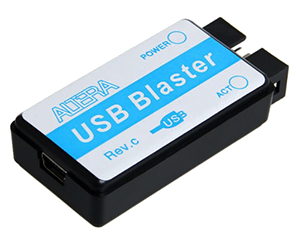
For a quick start with the programmer you need to buy adapter Altera USB-Blaster C and install the Altera USB-Blaster driver for your OS.
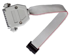
Also you can use the LPT port and LPT Adapter. This work with older computers and is not relevant now.

Drivers install
The 'uFlash' require original: Altera USB-Blaster driver Winand the Direct D2XX driver from FTDI: D2XX
Installation instruction for Linux OS: USB-Blaster driver for Linux
Windows LPT port driver are available here: InpOut32 (x86 x64)
Port configuration
When using different adapters for programming, you must configure the interface. LPT or USB port is specified in the 'uFlash.cfg' file. To choose the port to use, change the string: port=lpt or port=usb in the 'uFlash.cfg' file.
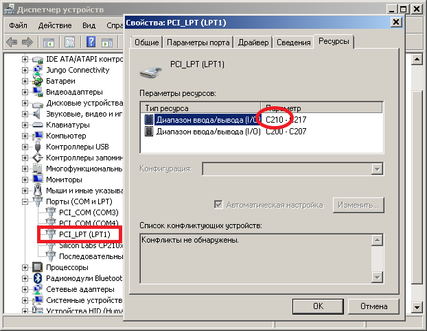
If yours LPT base address is different from the standard one (0x0378), it can be specified as follow string: lptaddr=0xC210. Your current LPT address can be found in the PC 'Device manager' panel.

How to add a new chip
If the chip you are looking is missing in the 'uFlash.cfg' file, you can use the chip datasheet for the add required parameters, and include corresponding line to this file yourself. Some chips, for example AT45DB161, do not have the JEDEC autodetection code. In this case you need add -n=AT45DB161 name forced option to the command line, and specify parameters for your chip like: name=AT45DB161 line of 'uFlash.cfg'. For new MCU chips, you can do it similarly. See 'Chip ID' field & 'Chip version' for add new configuration string.Options
If you run the program without parameters, it outputs a list of possible options.It is convenient to use batch files for different configurations.
The program folder contains the following examples of *.bat files:
• erase.bat - chip full erase
• write.bat - program chip
• verify.bat - verify programming
• dump.bat - reading data from the chip
• show.bat - show dump on the screen
• compare.bat - compare dump with the file
Other files included in the program folder are:
• config.cfg - configuration of port
• flash_db.cfg - database of FLASH memory & configurations
*.bat file examples for program embedded OS are available here uClinux flashing
* Resurrecting the TI 'CC Debugger' solution are available here CC-debuger recovering

Downloads
Application download:
uFlash programmer (Windows) v3.0
Old version: ver 2.8.7
SPI prog v2.8 (Windows x86)
SPI prog v2.8 (Linux x86)
Download drivers:
Altera USB Blaster Win
USB D2XX drivers
LPT driver WinNT
LPT driver Win7-10
Adapters and connections:
Connect SPI Flash sch
Connect TI CC2511 sch
LPT Adapter sch
Altera USB-Blaster Doc
 en
en


