-
 en
en
T-962 more improvements
Deep modernization of the Chinese soldering oven. Based on the project: T-962 reflow oven improvements
Why this article appeared.
Our lab needs assembled miniature PCB for electronic prototypes. Previously, we had ordered PCB with assembly from Chinese factories, but the last few orders results was very disappointing. In fact, we lost half a year of time, thousands of dollars due to incorrect assembly and soldering. We tried to move the assembly in-house purchased the popular oven T962. But practically, in reality the only thing that more or less works for this PCB oven is the iron box. Hardware and software are practically unusable and destroys components by overheating. There are several attempts on the Internet to fix these problems with workarounds. Our modifications and software makes this oven of very high quality and suitable for practical use. Now it works well enough, approaching the quality of soldering to professional equipment.Calculation of uniform illumination of the PCB plane
First of all, we have to get around the many problems with unsoldered components. To do this, we need to calculate the optimal positioning of the heaters. So that there are no shaded areas and the heating energy is evenly distributed over the of the PCB circuit board surface. We must calculate the required number of infrared radiation sources and their location.Let us take an example from the technique of illumination. Let there be a light source at a distance a above the plane. It will illuminate the surface. What is the energy of radiation falling on a unit area of the surface per unit time. See picture:
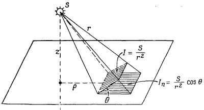
We assume that the source is spherically symmetric, and the light is radiated equally in all directions. Then the amount of radiated energy passing through a unit area perpendicular to the light flux changes inversely proportional to the square of the distance. Obviously, the intensity of light in the direction of the normal is given by the same formula as the electric field from a point source. If light rays fall on a surface at an angle θ to the normal, then I, the energy falling on a unit surface area decreases by a factor of cos θ, because the same energy falls on an area 1/cos θ times larger. If we call the strength of our source S, then In, the luminosity of the surface, is:
where er is the unit vector in the direction from the source, and n is the unit normal to the surface. The illuminance In corresponds to the normal component of the electric field from a point source with charge 4πε0S. Given this, we see that for any distribution of light sources we can find the answer by solving this equation. We calculate the vertical component of the field on the plane from the charge distribution in exactly the same way as for the light sources.
We need the PCB to illuminate evenly. We have long tubes of IR lamps radiating evenly along their entire length. By placing the tubes in regular rows on the ceiling, which is at height z above the PCB. What should be the optimal distance b from the tube to the tube if we want the surface illumination to be uniform to within one thousandth?
Answer:
1. Find the electric field from a set of uniformly charged wires with a gap between them equal to b.
2. Calculate the vertical component of the electric field.
3. Determine what b must be equal to so that the waviness of the field is not greater than one thousandth.
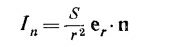
We saw that the electric field from a series of charged wires can be represented as a sum of terms, each of which gives a sinusoidal change in the field with a period b/n, where n is an integer. The amplitude of any of these terms is given by the equation below:
We only need to take the case for n=1, we want to get the field at points not too close to the lamps. To get a complete solution, we still need to determine the coefficients Ap, which we have not yet found (they are found by direct calculation). We only need to know A1, then we can estimate its magnitude by considering it equal to the mean value of the field. The exponential multiplier then gives us immediately the relative amplitude of changes. If we want this multiplier to be 10-3, then b is 0.91z.
If we make the spacing between the lamps equal to 3/4 of the distance to the ceiling, the exponential multiplier will then be 1/4000, and we have a reliability factor of 4, so that we can be quite sure that the lighting will be constant to within one thousandth. The exact calculation shows that A1 is actually twice the average field, so the exact answer would be b=0.8z.
According to these findings we find a simplified calculation formula. The distance between the centers of the heaters should be calculated by the short formula: x = h / 1.34 Where h is the distance from the center of the heater to the PCB board surface. The heating chamber have distance h = 40 mm, so the heater spacing should be 30 mm.
Adding additional heaters
As we calculated earlier, the heater pitch should be 30mm. In the original design of the oven this is not respected. Therefore, we disassemble the housing. Take out the soldering chamber and cut grooves to install additional heating tubes.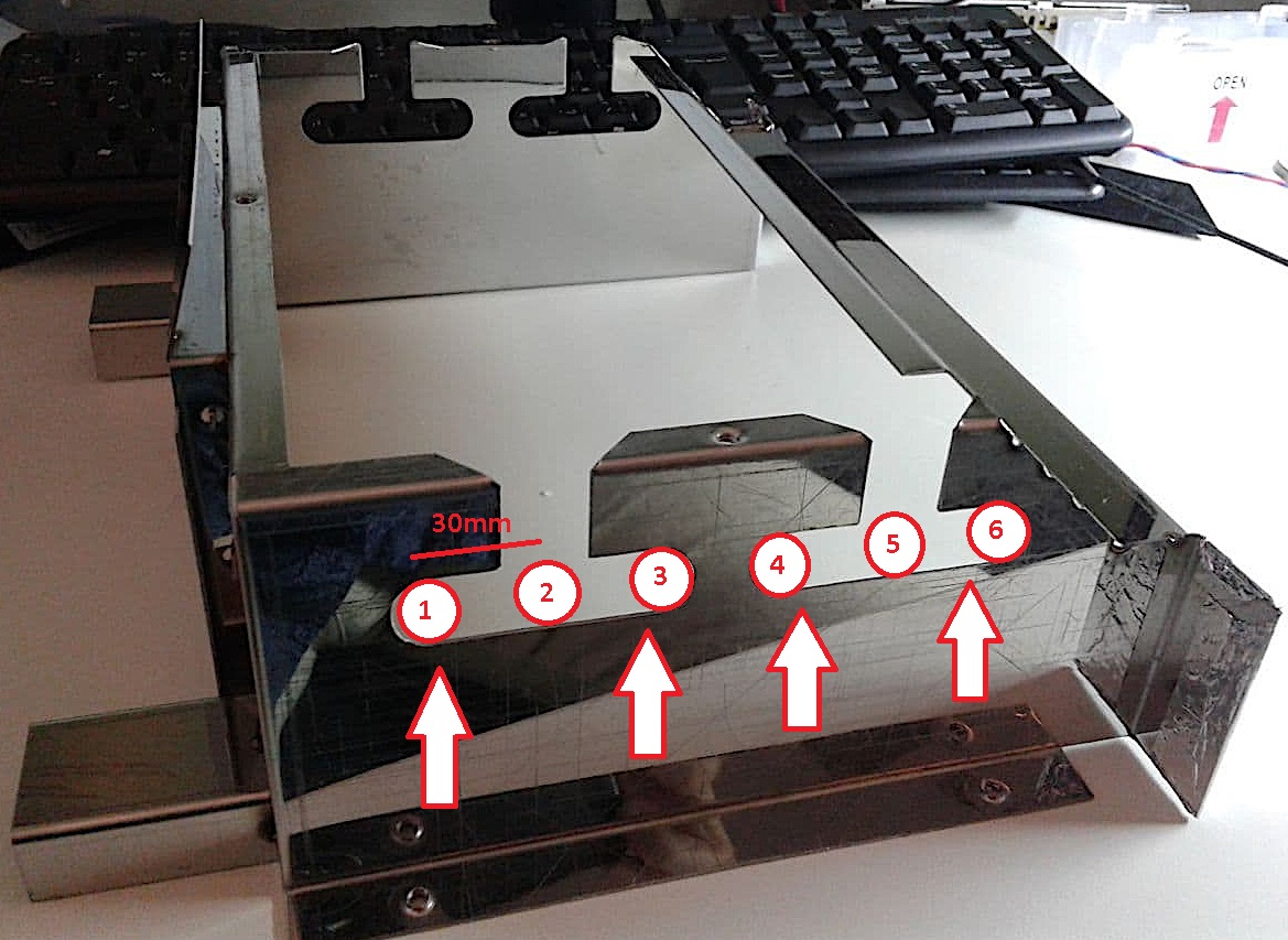
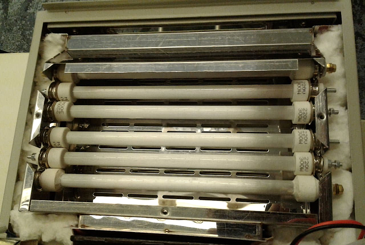
The heating elements have been completely replaced with new ones. The old ones had to be thrown out - they had assembly defects, the сhinese had not wound the coil evenly.
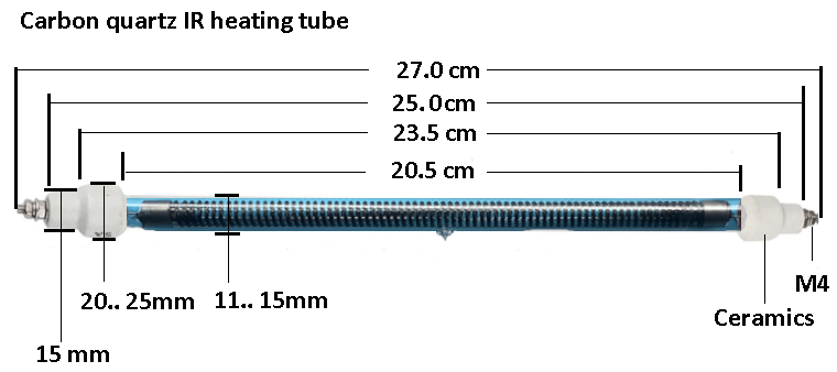
The best heater for soldering are the ones that have the longest wavelength radiation. These are lamps with a carbon heater. They are very fast and the PID works great with them. In the picture below you can see the dimensions of the heating tubes for the T962. I couldn't find these so I bought the regular ones 220v 300Watt from this store: Infrared Quartz Tube Heater 25cm
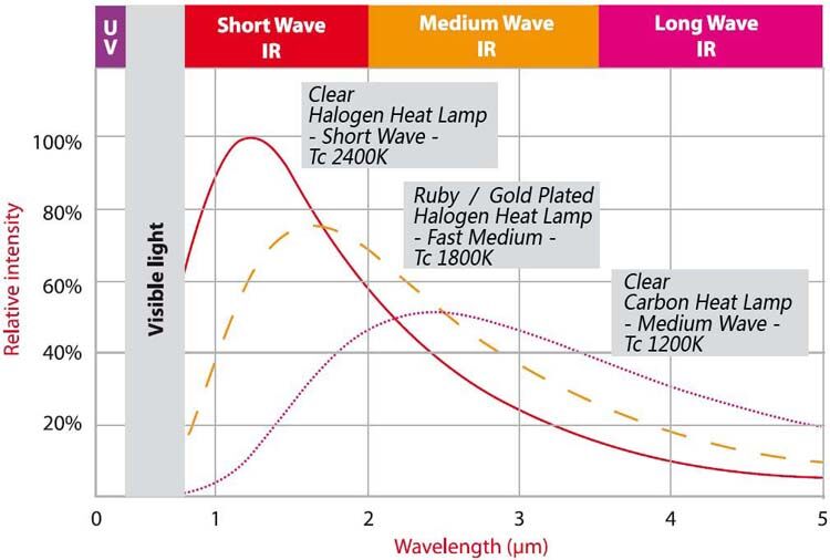
The less heated the coil of the lamp is, the more long wavelength it radiates. This is very suitable for us. All the heaters are connected in parallel. The total power is 1.8 KW, but this is never used due to the partial heating mode. There is no need to change the controller triac, it has enough power to work safely.
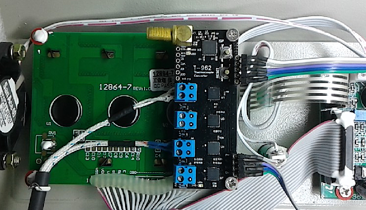
MCP9600 Temperature Sensors Converter
Adding a high quality temperature meter board. The MCP9600 chip provides very high accuracy and stability: +/-0.5°C typical Hot-Junction temperature measurement accuracy. There is no need to calibrate the sensor later on. For a full description see the Microchip website MCP9600
The board contains:
1. 4x Thermocouple Converters.2. Bluetooth communication chip with PC.
3. External Bluetooth antenna connector.
4. Reset button for manual reset.
5. ISP button for manual programming.
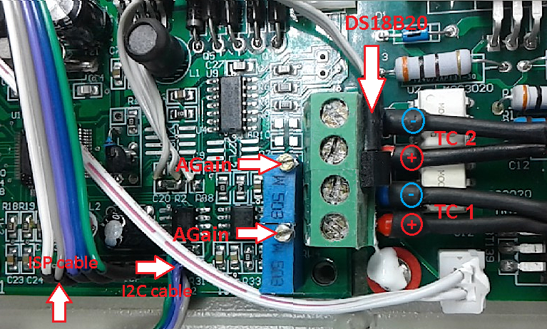
6. Connector for I2C interface to oven.
7. Connector for ISP interface to oven.
8. Connector for SPI interface.
9. JTAG for BT chip.
Sensors PCB schematic
At first the MCP96L01 chip was used, but after tests it had to be replaced by the MCP9600. Because the MCP96L01 stopped the measurement when the thermocouple touched the ground. This is probably a design defect of the chip. Do not use the MCP96L01 - it It can cause catastrophic overheating of the oven.
You can purchase fully assembled and programmed,
ready to use 4x channel MCP9600 sensing board. With sensing accuracy: ±1°C.
The oven can be connected to PC via the embedded Bluetooth.
T-Sensors check utility

T-Sensors check utility
CP2112 USB driver
CP2112 debug board USB to I2C gate
Use the configurator to check or calibrate the sensors. The program quickly changes the settings and you can evaluate the quality of the sensors in real time. Use the CP2112 board USB to I2C adapter from Aliexpress for easy connection to your computer. The PC adapter is connected with 4 wires with the same name : VCC-3.3V, GND-GND, SDA-(I2C-SDA), SCL-(I2C-SCL).
Digital filter
Use of the built-in Digital Low Pass filter brings serious advantages. The MCP9600 chip contains integrated a hardware digital filter (DSP). The presence of the filter is very important for quality temperature control. It suppresses high-frequency noise and the PID differential channel works correctly. The filtering quality can be set from the 'Noise reduction filter' box. For common casess select its 'average' value.Sensors calibration
We will calibrate the sensors to the middle of the measurement scale = 100°C. It is most convenient to do it by the value of the boiling point of water.The MCP9600 supports 8 different types of sensors. I use the cheapest Type K thermocouples for the range: -40..+400°C. They are accurate enough for all soldering applications. They were purchased here: Aliexpress K-type

Connect thermocouples to the blue PCB connectors. Observe the correct polarity of the wires. Connect (+ Alumel wire) to the upper terminal, connect (- Chromel wire) to the lower terminal.
Heat a glass of water to boiling and lower the balloon junction of the thermosensors into the water to the center of the vessel. Run the configurator program and see the result of the temperature measurement.
| Altitude, ft (m) | Boiling point of water, °F (°C) |
|---|---|
| 0 (0 m) | 212°F (100°C) |
| 164 (50 m) | 211,6°F (99,8°C) |
| 500 (150 m) | 211.1°F (99.5°C) |
| 1,000 (305 m) | 210.2°F (99°C) |
| 2,000 (610 m) | 208.4°F (98°C) |
| 5,000 (1524 m) | 203°F (95°C) |
Installing the sensors PCB
You need to make two flat flex cables with connectors.The first cable connects to the ISP connector on main controller board. Through this cable the oven processor will be able to data exchange to the computer via a wireless Bluetooth.
The second cable is the I2C interface and the +3.3v power supply. Here the oven processor reads the temperature values from the thermocouple chips.
The last cable, this is the RF cable. It is used to connect the external Bluetooth antenna. The external antenna provides a reliable connection to the oven at a distance of about 15 meters. In the photo below you can see the device already installed.
Oven controller modification
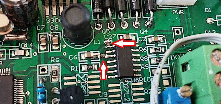
Should replace the factory installed 27L2C dual OpAmp with a pin compatible Analog Devices chip AD8552ARZ. The AD8552 also a dual OpAmp, but with zero drift: 0.005uV/C, and low offset voltage: 1uV. Measurements will be more accurate and stableInstall two additional resistors 1.5... 3 Kom to ensure that the heater does not spontaneously turn on when the firmware is updated. This could cause a fire. The resistors should be soldered to chip U9:
U9 pin 1 to +3.3v,
U9 pin 3 to +3.3v.
Complex strategy for a simple oven
In a simple device design, we have no bottom board heating, no multi-zone heating, no conveyor belt. Therefore, using the standard method and soldering profiles from a professional furnace will not lead to success.If your PCB board has components of different sizes and weights and different heat capacities. Different waiting times for warm-up will be required, so that the contact pads under the larger components have time to reach the melting point temperature of the solder paste.
If the temperature profile moves too fast, the massive components will not have enough time to warm up and the soldering event will not occur. Small components will solder but large components not.
For this obvious reason, the soldering algorithm will not be simple. It must be adaptive and smart enough. As the process progresses, it has to analyze sensor data and dynamically change the speed of the profile until the set temperature is reached.
We should use several temperature sensors on the PCB at the same time. The first one should be mounted next to the most thermally sensitive component, e.g. the plastic LED housing. The next sensor is next to the most massive component like a transformer. Add the sensor in the center of the board, where the temperature will probably be maximal. In the settings of the control software, should specify in which role sensor is used and its coordinates on the board.
We will use two upper temperature sensors to limit overheating. These sensors are located directly near to the heater tubes and have a low moment of inertia. In the areas of rapid temperature increase, due to the significant transport delay of the main control loop, The PID will ramp up the heating power to maximum and this in a few seconds can melt the plastic components with shortwave IR-light radiation. To prevent this from happening, let's add to the system a protective algorithm for dynamic limit the heating power.
At the same time, it is necessary to calculate the permissible electrical power, to be supplied to the heaters. If the heating energy is less than the optimum - the process time will be delayed, the solder flux in the paste will boil out and the soldering will not comlete well. If the heating is too fast - the radiation will damage the delicate plastic components. Because plastic have poor thermal conductivity, and t-sensor on the PCB have the delayed response. The overheating point is difficult to detect in right time.
Soldering in a single chamber furnace
It is important to determine the basic principle of soldering in a single-chamber furnace - there must be many lamps for heating... So that the array of lamps works without significant overheating relative to the board temperature and the PID regulator does not enter into saturation. It is important that the lamp coil heating is as low as possible and the radiation of the lamps is as long wavelength as possible and does not go into the visible red or orange range of the spectrum. If you have only one or two tubes in your furnace - to heat up the contents of the soldering chamber, you definitely have to overheat them considerably! In this case, the performance of the system will be the worst. Almost all single chamber furnace modifications that I have seen contain this very error. The lamps are few and glow in the visible part of the spectrum. In a "proper" soldering furnace, you shouldn't be able to see the operation of the lamps with your eye.
And so, if you have installed a lot of additional lamps, the dependence on their speed will no longer be critical. The power will be enough to heat up the board with only by long wavelength radiation. The main delay now will be the thermal inertia of a board with massive components. Such a board heats up slowly and cools down slowly. If you try to give more power to strictly follow the profile the lamps will go from the long wavelength range to visible red and the shorter wavelength light will melt and ruin the plastic of the component housings. This should not be allowed to happen. Therefore, when heating, should do small increments of temperature increase, e.g. +2 degrees. Take 1 step and wait until the temperature is established. The temperature step should be dynamically recalculated, automatically dividing the interval remaining to the point of extremum by the desired amount of temperature increment. It is possible to install an additional sensor for the intensity of visible radiation and limit the heating by it. In this case there will be no overheating of the components by the short-wave light radiation. Because the lamps will be in a small incremental current mode relative to the previous step and the board will warm up qualitatively and evenly. The temperature profile will strictly follow the temperature, but the time of its movement will dynamically change.
When we come to the point of flux activation, we should switch to the heating mode without power limitation. And then in the same mode perform fusion...
These algorithm and measures and the complication of the softwares will give us the ability to to assemble prototypes with high quality in a simple single-chamber furnance, without additional rework and damage to components.
Connecting via Bluetooth
Communication with the oven is supported via bluetooth. The program on the computer side will need use external usb bluetooth adapter based on the Texas Instruments CC2540 chip. This very cheap and high quality adapter can easily be buy on Aliexpress. For example Texas Instruments CC2540 with antenna
Load the firmware into the adapter
Use a TI CC-debugger programmer to load CC2540 firmware.How-to: 5.2 Hardware Setup for USB Dongle.
use the latest TI firmware from the product support page CC2540 BLE STACK. File: Texas Instruments\ BLE-CC254x-1.5.1.1\ Accessories\ HexFiles\ CC2540_ USBdongle_ HostTestRelease_ All.hex
Or use CC2540 USB dongle
Suitable any similar USB dongle witn preloaded standard TI BLE stack. Devices available on Aliexpress or Alibaba.For example: CC2540 USB Dongle

Install USB driver
When you connect the adapter to the computer, the system ask USB driver for CC2540, it can be find here: USB driver. Then you can download a ready-made or self-compiled T962 PC application. T962 PC project. Don't forget to program into the MCP9600 Thermocouple nRF51822 chip the t962nrf firmwareT962 PC Software
'T962.exe' will be able to to quickly change many oven important settings and operation modes.
Now should open the Tab 6 the program 'T962.exe' and connect to the oven. Use button "Bluetooth". If all is correct, you will connect in 1-3 seconds after the program starts. The next step is to update the oven firmware. Press the "FW Update" button, select the newest oven firmware file t962nrf firmware and wait for the process to complete.
Calibrating the top side T-sensors.
Open the Tab 1 "ADC" and calibrate the temperature sensors of the heater.

The calibration can be done at two points 0 and 100 degrees. Before, set the parameters 'Offset' = 0 and 'Gain' = 1.
Immerse the thermocouples TC1 and TC2 in boiling water. Use the trimmer resistor on the controller PCB board, set the sensor output to 100 degrees.
Now short the thermocouple with a short wire or tweezers. The reading on the display should be the same as the value from the CJ temperature sensor. If it does not match, enter a correction constant in the 'Offset' edit box. The 'Offset' parameter corrects the parasitic shift of the zero level of the analog thermocouple amplifier.
Disconnect the wire and repeat the calibration process several times. The 'DGain' parameter is needed to fine tune the gain without disassembling the oven. Do not need make this settings absolutely exact. Because of the poor quality of the Chinese circuit design, this sensor will still drift. But this is enough for us to function properly.
Thermocouple Sensors configuration.
Go to Tab 5 'T-Sensors' and configure which ones you want to use. In the example below, you see. Normally, I turn off and do not use TC1 and TC2 at all. Because the temperature values of these sensors and the PCB are very different and cannot be used for quality soldering.

Additional T-sensors (MCP9600) are used for precise soldering control. I enable 2 or more channels, depending on the size of the PCB board and the weight of the components. Then I start the soldering of the first board and see the output of the temperature table and choose the settings.
In this case installed the first one next to the miniature plastic component. The second next to the chip and the third sensor in the center of the board. The TS buttons show the dialog box for the individual setting of the PCB sensors.
Heater configuration.
Open the Tab 3 "Heater". Here you should set the control parameters for your hardware: 'Heater Total Power' - total power of heaters installed in the soldering chamber. 'Heater Power Limit' - at this level the maximum energy supply is limited by the rapid increase in heating. 'Heater Temperature Limit' - parameter dynamically limits the heating to this temperature level. 'Fan Speed' - determines the speed of ventilation in the chamber when soldering in heating mode.
The 'Heater/Fan manual control' handles provide direct access to control of the heater and fan. Be careful, in this mode the automatic control is disabled and you can easily "fry" the contents of the soldering chamber.

PID configuration.
Open the Tab 2 "PID". Run tests and see the temperature of the pcb matches witch profile. The difference should not be more than 2..5 degrees. I easily got a deviation of no more than +/-1 degrees. If the error is larger, you need to adjust the parameters of the PID regulator.

For this purpose set the temperature in the chamber, for example 'Set Point' = 100 degrees. Press the 'Run Manual' button, the oven will start heating. By adjusting the P coefficient, get close to 100x0.9 = 90 degrees. Then adjust the minimum coefficient I so that the temperature is close to to the set point of 100 degrees. Then, by turning the heat on and off, adjust the minimum D factor. At the best setting, the temperature should be set as quickly as possible with minimum overshoot. Below you can see the sequence of optimum manual adjustment of the PID coefficients.

Firmware use a modified PID algorithm that prevents saturation of the Integral channel. This allows quickly reach the operating point without overshooting the temperature. The first graph shows the behavior of the usual classical PID regulator, on the second - modified PID. Here the temperature overshoot is minimal.


System efficiency test.
Now you can go to the 'Reflow' Tab and select the 'Ramp Speed' profile to check. If the PID has been set correctly, you will be pleased with the result.

Ramp Speed Test shows tremendous power and excellent accuracy of furnace. Made a quick transition to almost 200 degrees step in 15 seconds. Temperature drift no more than 2 degrees. Thiswill potentially will be enough to perform any standard solder profile.


These graphs show the thermal profiles of a board soldering with medium-sized components. The profiles are fairly accurate. In the cooling section, the board cools down slower than required, because there is considerable thermal inertia and not enough cooling fan power. It should be three times more powerful. But it's not critical for me. I don't want to change the fan, I'll wait until it cools down a few minutes longer.
Note the graph of the power control (yellow line). The energy is supplied smoothly, without sharp peaks. This protects the electronic components on the circuit board from damage by shortwave IR radiation.
Soldering profile management.
Open the Tab 4 "Reflow". Here you can select the desired profile for soldering from the list. There are already 11 various profiles stored in the oven memory. They cover the entire commonly used temperature range.
| Manufacturer | Marking | Peak Temperature |
|---|---|---|
| Amtech | NC-31 | 160°C |
| ChipQuik | SMDLTLFP | 165°C |
| Kester | NP505-LT | 190°C |
| Amtech | 4300 63S/37P | 215°C |
| Kester | HM531 | 230°C |
| ChipQuik | SMD291AX | 235°C |
| ChipQuik | TS391AX | 235°C |
| Amtech | SynTECH-LF | 245°C |
| ChipQuik | SMD291SNL | 249°C |
| Kester | R276 | 250°C |
| Kester | NP505-HR | 250°C |
| Kester | NP545, NP560 | 255°C |
| Profile | Preheat 4..7min | 50°C |
| Profile | Preheat 4..7min | 75°C |
| Custom Profile | 48 points | 20..350°C |
Also you can load any custom profile from a file and write it into the oven memory in the section 'Custom Profile'. Press button 'Settings' to select the desired soldering parameters. If needed, you can enable a soldering Log and save it as a picture or as a file. The button 'Launch Reflow' starts or stops the process.

Analysis of the soldering schedule.
Use the "T-Graph" button to immediately get a report on the passed soldering procedure.

As seen above. Now we used 4 sensors: TC1, TC2, TS1, TS2. Soldering started after 5 minutes of preheating the camera and PCB at 50 degrees. If the chamber is cold, always do a preheat. This will greatly improve the quality.
Next we see, the top sensors TC1 and TC2 monitor the intensity of IR light and do not go beyond the damage temperature of the compornents, the limit is set at 220 degrees. Therefore, there is no current limit for the heaters.
Thermal sensors TS1 and TS2 are located on the PCB. The temperature difference between them is about 30 degrees. This indicates uneven heating of the board. In this case, a simple algorithm of following the thermal profile in time is performed, so there is no automatic stop and waiting for PCB temperature equalisation. Although the average PCB temperature is the same as the required PCB temperature, the soldering will not be of high quality. The TS2 side will be underheated and unsoldered.
To follow the thermal profile exactly, you can switch on convection in the chamber, stirring the air inside intensively. Or if there is no internal fan, make short stops and wait for the board to warm up. But in this case we can no longer follow the time parameters of the thermal profile. Although the soldering quality will be better.
Creating and add custom profile.
Find the documentation for the solder paste you need. In it, using the graph plot the temperature vs. time. Write this data into your *.csv file. This can be done in Excel or in an ordinary text editor. In the first column should enter the time values with increments of 10 sec. Then column the temperature. The profile should end with 0. Look for examples files in the 'Profiles' directory.

Open the file in the program and check for errors. Then press button 'Write' to save the file into the oven memory. Unfortunately, due to the small EEPROM memory size only 1 buffer are available.
Safety measures
Unfortunately, the electronics of the oven controller was made illiterate. It did not provide any safety and overload protection functionality. There is no zero crossing sensor for the main power voltage. Therefore, breakdowns of power elements are likely. If the processor will suddenly freeze, and at the same time the heating was on, a catastrophic heating up and melting of the furnace with the following fire. Therefore, never leave the oven unattended while it is in operation. You should always be ready to turn off the power manually.If you use the firmware update function, the "FW Update" button. Be very careful! For the same reasons, due to programming failures, the heater and fan can switch on by themselves. If the main fan suddenly turns on during programming - immediately turn off the power to the oven manually, so that it does not have time to warm up.
About software
We provide free source codes of simple version of T962.exe application for PC + firmware source code and *.hex file for oven. You can download these from the links below. Use them as base demo, but here removed smart algorithms and enhancements. If you need precision soldering with smart features. Buy our professional version of the software and firmware. The additional price is $250. From time to time we refine the software and firmware and add additional functionality.If you have any additions or bug fixes to the programs code, please send them in, they will be included in the release.
Questions
Can I do these improvements with a T-962A also?Yes, you can do that. The distance between the heaters must be recalculated as described above. Connect the heaters in series so that their total power is not exceeded by the controller. Everything else is similar.
For now I have the 962A version with the cold junction mod. Is it possible to run firmware on that hardware without further modification?
You can use firmware without additional thermal sensors. To do this, disable all MCP9600 Sensor (check boxes) on the Tab 5. And turn on the "Top Side Heater Sensor". In this case the oven firmware will only use the cold junction. But the temperature accuracy will be worse.
How to connect to the oven via UART without bluetooth?
To program the device with the new code, you have to buy or make a UART-COM adapter anyway. It is much more convenient to use a bluetooth module. You can buy any module built on the nRF51822xxAC (256K Flash 32K RAM) chip and connect it to the pins of the oven controller board. For example this one: nRF51822 BT module Check below the "Thermocouple pcb sch" pdf. You need to connect 5 pins "ISP", power +3.3v and 2 pins "I2C". For the Bluetooth module to work correctly, it must be reprogrammed with: nRF51822 firmware
How do I program the nRF51822?
You need to fill 2 files: s130_btstack.hex and t962-nrf.hex. For this to be successful, the chip must have 256K Flash 32K RAM. Don't buy smaller size memory chip - it don't work! Use any programming method available to you, there are enough descriptions on the internet.
How to remotely update the oven firmware?
Open the application last Tab 'Common'. Connect to the oven. Press the "FW Update". Select the firmware file. Wait for the app to reprogram the device.
Can I not use the extra sensor board?
I'm not going to talk you into using additional thermocouple board. But you won't get anywhere without a few temperature sensors. Your experiment will only end in wasted time and damaged PCB boards. In the example above, with 2 sensors we apparently have a rather poor alignment. Analyse the graph of temperature distribution over the PCB surface. The difference in sides is more than 30 degrees, and that is bad for optic components. The difference should be no worse than 5 degrees. With automatic aligning algorithm turned on, it turns out to be about that. But you can never do it without multi point measurements.
Downloads
Files for work:
T962 PC Win App (exe)
T962 USB driver (for CC2540)
Firmware BT dongle (CC2540)
Firmware Oven (LPC2134)
Firmware T-Sensors board (nRF51822)
Help:
T-Sensors check utility (exe)
How To flashing firmware
For developers:
T962 PC app source code (MSVS)
Oven firmware source code (IAR)
Old original version compiled by IAR:
Oven source code v0.5.2
Oven firmware v0.5.2
Circuits and chips:
T962 controller pcb sch
Thermocouple pcb sch
Chip MCP9600
Homepage
Terms & Conditions
About Us
Privacy Policy
Business Info
Contacts
Payment
Shipping
Send Msg
Singapore 2026


